The second phase of this project involves the use of a CAD (Computer Assisted Drafting) software to convert my physical model into a three dimensional virtual model. The software I will use is known as RHINOCEROS. With the help of various measuring Tools, I am able to determine the specific proportions of the basic forms which make up my physical model and then recreate them in the computer.
The process of modeling itself is honestly easier shown in real-time than explained. In short, however, it basically involves determining the most basic forms of which an object is comprised, creating them, and then combining, subtracting, intersecting or modifying them to create the desired form.
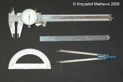
Some of the most important tools that I use in the conversion of a model from physical to virtual are a good set of calipers, a decimal centimeter rule, and a standard protractor. The combination of these three tools gives me the majority of the dimensions that I need in order to recreate most real world dimensions and proportions with a fair degree of accuracy.
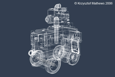
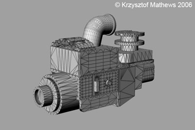
The resulting virtual model is what is known as a WIREFRAME model. It has all of the proportions and structure, but it lacks any textural detail.
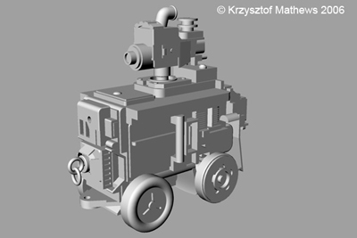
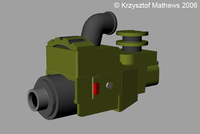
A quick render indicates that the surface is a basic default grey.
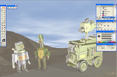
The next level of development is surface treatment. What the piece needs now are TEXTURE MAPS that are able to conform to the specific geometry of the finished model. Fortunately, RHINO allows for this in the output of the model to a Wavefront (.obj) file format that supports specific data known as UV coordinates that allow one to create a specific tailored texture map. Above, you see the model bedecked with the appropriate maps.
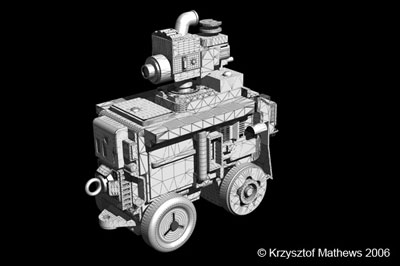
Here, you can see where the various colored elements in the map are applied to the camera model so that there is clear registration. This editing is done in a 2D application such as Adobe Photoshop. The same process is applied to all of the individual components of the virtual model.
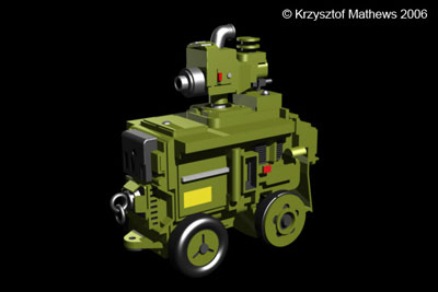
Once all of the appropriate texture maps have been applied, the model is now ready for a preliminary RENDER, in order to make sure that everything looks right. A render might be considered as the equivalent of literally taking a picture of said virtual object in a particular application. The two applications that I favor for this work are Carrara 5.1 and Bryce 5. These applications allow me to adjust lighting and cameras as if I was conducting an actual photo shoot, thus giving me a good deal of control over the final image.
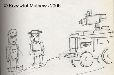
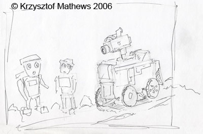
At this point, I now have all the resources prepared for scene creation, but before I begin, I will spend several days doing sketches and preliminary drawings.
Every digital piece that I create begins as a series of sketches. I do this for a number of reasons, foremost being that that sketching is a quick, effective, and resource-efficient means of blocking out key elements, determining the basic color palette and composition, and experimenting with a variety of options and scenarios. Indeed, in my Illustration training, sketching was considered an absolutely ESSENTIAL part of the working process.
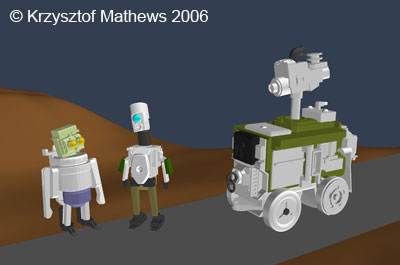
Once the basic layout has been decided on, the next phase is the actual setup of the scene. Once I have imported the various models into an application like Bryce or Carrara, I then move them around in a very low-resolution mode, in order to allow the computer to update large changes far more quickly. One might say that this is much like the equivalent of a plainclothes rehearsal for a theater production, in which blocking is addressed before getting into the nuances of costumes and props. It is at this point that I might choose to create various terrain meshes, which will be adjusted later.
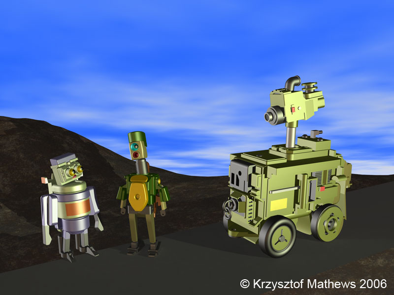
Once I have decided upon a final composition for my scene, and adjusted all of the details of the characters, terrain, props, lighting, and atmospheric effects accordingly, I will then create a fully rendered scene at a high resolution of approximately 300 DPI (Dots Per Inch) so as to achieve a sufficient level of detail for the final reference image. This rendered image I save as a TIFF file, as it is a non-lossy format.
So now that I have a rendered image, I am ready to bring it into Adobe Illustrator and redraw the scene. The first question that might well come to mind is “Why?”
There are a couple of reasons.
1.) Simplification
A number of years ago, I was busy making a graphic novel with straight rendered images of my characters. One day, I showed one of these scenes to my father. Given that the characters were only loosely anthropomorphic and were presented as heavily textured figures against a textured background, he found that he was having difficulty in understanding the composition. I agreed immediately. Clearly, there was too much information. I needed to clarify the image. At that point, I began to look at the work of various Japanese artists, including the contemporary Japanese artist Takashi Murakami and realized that the emphasis on line and “flattening” of the background could be employed in my own work. In using Illustrator to redraw the scene, I can achieve this effectively and thus bring crispness and clarity to my illustrations. Illustrator allows me full control over everything from color palette to atmospheric and textural effects, so that the scene does not become too busy.
2.) Scalability
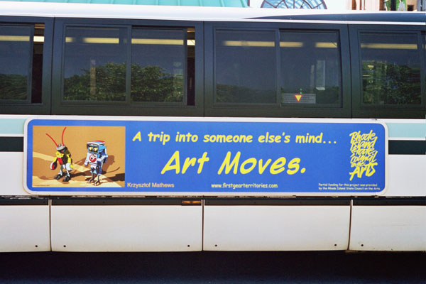
Illustrator images are VECTOR graphics. Unlike traditional RASTER (Bitmap) graphics, they are ultimately scalable with no loss of fidelity or increase in memory. This means that they are adaptable for everything from web to print in any size I might choose. A few years ago, as part of the “Art Moves” Project funded by the Rhode Island State Council on the Arts, I even had my images on the sides of several Rhode Island RIPTA (Rhode Island Public Transit Authority) city buses!
But enough background…Lets see some drawings!..
To begin, I will take the Rendered TIFF Image and place it in Illustrator as a background Guide layer that is faded to 50% saturation and then locked (to avoid tampering with the source image). Over that layer, I create several layers, each dedicated to a separate element of the scene (Nok, Wibble, Science Cart, Terrain, etc.), thus allowing me to concentrate on specific parts of the image at any given time. I then use the Pen and Shape tools to trace the underlying image. The Pathfinder tool allows me to combine, divide, and intersect these basic shapes and forms. For some of the more organic shapes, I may also use the Pencil tool to capture a more freehand quality for a specific line or element.
The final phase after the meticulous process of tracing the underlying image is that of coloring the individual segments. Not only have I traced the masses and structural forms, but I have also traced the bands of color and shadow, as well as highlights and reflections as individual shapes. All of these will now need to be given color, by means of using the Eyedropper tool to “catch” the color from the underlying image. Often, I will find that I need to make various subtle adjustments and decisions in order to better emphasize or downplay certain parts of the image. I often think of this process as somewhat akin to the work of creating a stained-glass window, in which every single colored element is cut and fit to the larger shape.
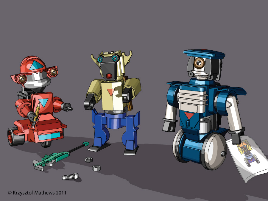
And here we have it…The final finished image, ready for Print, Web, or Multimedia.
Now that we’ve gone through the whole process, there may still be a few questions….